
On this page
IN BRIEF
Get the floor model, template and supplied operations on one offer
Specify a replacement floor that fits the current vehicle and its duty. Verify the opening and supports, identify the upper face, datum, joints and holes, and request the relevant data for the proposed panel and surface. Compare finished replacement pieces, processing, protection and spares against the same vehicle and drawing revision.
- Use a dimensioned template with a clear orientation.
- Keep loads and support details with the material request.
- Describe contamination and cleaning for the surface evaluation.
UNDERSTAND THE DETAIL
What plywood specification is needed for a trailer floor?
Identify the current vehicle/platform, complete floor arrangement, actual supports and fixings, wheel/contact loads and service conditions. Request the offered core/lay-up/gauge/bond and relevant directional data with the selected surface. Keep the responsible vehicle/floor review and the agreed template with the proposed replacement.
For a floor divided into several pieces, mark the traffic direction and each joint on the template. Identify access hatches and wheel cut-outs independently. If the old floor is damaged or swollen, verify its dimensions against the vehicle before treating it as an accurate cutting pattern.
- Fit
- Overall outline, datum, cut-outs and tolerances required for the actual opening.
- Load path
- Panel spans, supports and fixing details for the responsible design assessment.
- Surface duty
- Traffic, footwear or wheels, contamination and cleaning conditions for the required surface evaluation.
How should the surface be evaluated for wet or contaminated use?
Describe the expected footwear/wheels, dry or wet conditions, contaminants, cleaning and wear stage. Request the actual surface/product identity, named evaluation method, directions, conditions and results for that duty. Keep pedestrian slip and wheel/vehicle performance requirements in their stated scopes.
Continue with checking replacement panels on arrival.
Measure from a stable datum and verify the current opening
Choose a datum and drawing convention that the workshop and installer can reproduce. Record the vehicle/front direction, upper face and separate material/grain orientation. Keep the dimensional verification on the actual vehicle with the removed-floor observations; identify any altered bracket, worn hole, swelling or damaged edge that needs a revised detail.
Scroll horizontally to compare all columns.
| Item | Record or calculate | Order decision |
|---|---|---|
| Vehicle and revision | Vehicle/platform model or fleet item, current floor/part position, drawing issue and any chassis/support/fixing changes. | Review the replacement against the actual current arrangement and applicable vehicle requirements. |
| Outline and fit | Units, overall opening/outline, local widths, corner/wheel/hatch geometry, finished dimensions and permitted clearance at each edge/joint. | Verify the cut template and assembly fit using agreed measurement positions and stage. |
| Datum and holes | Reference origin, front/left/right convention viewed from the upper face; coordinates, hole diameter/profile and fixing/countersink detail. | Keep handedness and hole positions readable without relying on a photograph or automatic mirroring. |
| Supports and duty | Actual support/joint/fixing map, load/contact locations, wheels/footprints, traffic direction and loading/unloading/threshold conditions. | Request the relevant directional panel and connection data for the responsible floor/vehicle review. |
| Surface and protection | Textured front and reverse identity, conditions/required surface evaluation, actual cut-edge/hole/joint treatment, sealing/fixing/coating compatibility and sample. | Record the complete installed detail and the operations included in the proposed supply. |
Keep the template scale and face convention explicit
For a CAD or full-size template, state millimetres, revision, origin and a verified control dimension. Mark each F1/F2 outline, front and upper face, hole/cut-out identity and intended joint. Check any plotted/template scaling against the control dimensions and the actual opening before producing the full replacement batch.
Use the actual hardware and edge detail on a representative fitted trial. Record the finished stage at measurement and the specified fixing/contact requirements; a change in thickness, core, profile or fitting returns to the same vehicle and drawing review.
Measure the replacement as an assembly
Identify the vehicle or platform and the position of each floor piece. Record overall dimensions, joints, wheel housings, access openings and fixing locations. Show which face is uppermost and where the template datum is located.
Use the removed floor as reference material where useful, but check it against the actual opening and current arrangement. Damage, prior alterations or deformation can make an old part an incomplete template. Resolve the dimensional record before treating a photograph as a cutting instruction.
Include the service conditions that affect selection
Give the designer the traffic, wheel or point loads and support layout for the replacement floor. Have changes to thickness, core or fixings reviewed with that design before ordering.
For the working face, identify expected contamination, cleaning and relevant evaluation conditions. Keep the surface sample reference with any results requested for the actual proposed product. Plan how cut edges, joints and penetrations will be detailed for the intended service.
WORKED BUYING EXAMPLE
Example: a two-piece delivery-vehicle floor
Chosen front/rear floor-part record linked to a verified vehicle template.
The replacement has front piece F1 and rear piece F2; each receives its own position, template and material reference in the complete floor file.
Scroll horizontally to compare all columns.
| Item or observation | Record or compare | Next decision |
|---|---|---|
| F1 geometry | Front datum, opening outline and fixing locations. | Confirm the template against the vehicle. |
| F2 service | Rear loading area and wheel-path description. | Provide the duty and supports for review. |
| Shared joint | Joint location and edge detail between F1 and F2. | Confirm the complete replacement arrangement. |
What this means for the order
Send the template, panel specification and working conditions together. Ask the quote to list the material and processing so you can compare full sheets with prepared parts.
OPENING / CLEARANCE / PART
Measure the opening and allow for the finished cut part
Chosen rectangular planning inputs for the two-piece file: an opening 1504 mm wide and 4204 mm long, 2 mm outer clearance at every perimeter edge, and one 2 mm internal joint between equally long F1 and F2. These inputs demonstrate geometric bookkeeping; the actual vehicle arrangement supplies its own clearances, joints, support positions and cut-outs.
Scroll horizontally to compare all columns.
| Item | Record or calculate | Order decision |
|---|---|---|
| Completed part width | 1504 − 2 − 2 = 1500 mm for each rectangular piece. | Record local fit/corner/wheel details and the actual finished-width limits. |
| Total part length | 4204 − 2 − 2 − 2 = 4198 mm after the two perimeter clearances and internal joint. | Keep outer clearance and internal joint as separate drawing dimensions. |
| F1 and F2 lengths | 4198 ÷ 2 = 2099 mm each; check 2 + 2099 + 2 + 2099 + 2 = 4204 mm. | Locate the joint against the reviewed support arrangement before preparing actual holes or machining. |
Assign every hole and access cut-out to the part’s datum, current revision and installed face. Distinguish fit clearance from saw loss and from a mating profile’s geometry. Include the completed edge/hole treatment in the fit and fixing trial before the repeated cut schedule is accepted.
Quote the replacement pair and preparation needed
For the same chosen rectangles, select 1525 × 3050 mm sheets and a 10 mm trim at each outside edge, leaving 1505 × 3030 mm. Hold each 2099 mm direction along the selected sheet length. One 1500 × 2099 mm rectangle fits; two stacked lengths plus a chosen 3 mm cut gap require 4201 mm. The stated layout therefore uses one sheet per piece.
Scroll horizontally to compare all columns.
| Item | Record or calculate | Order decision |
|---|---|---|
| One vehicle set | Two 1500 × 2099 mm rectangles: 2 × 1.5 × 2.099 = 6.297 m²; one F1 and one F2. | Match each rectangle to the actual outline, orientation, holes, joint and full construction. |
| Gross sheet input | Two 1525 × 3050 mm sheets: 2 × 1.525 × 3.05 = 9.3025 m². | The chosen rectangular area is 6.297 ÷ 9.3025 = 67.69% of gross sheets, before actual machining/selection. |
| Reserve or another vehicle | Price named reserve positions and each vehicle/revision quantity separately, then review the combined cut allocation. | An offcut or same-size blank needs the relevant outline/material/fit review before it is assigned to another position. |
Compare the price for a complete vehicle set, including the panel, cut-outs, drilling, edge treatment, sample checks, labels and packing. Add installation work still needed, and use the same thickness, bond, surface and delivery requirements for each option.
For repeat fleet supply, retain the verified template, full panel model, fitted detail and part/pack references. Record a changed vehicle, support, hole map, surface or board construction as a new reviewed item before it is mixed into the current order.
Request surface results for the conditions of the job
The HSE 2012 flooring slip-assessment sheet explains the relevance of footwear, contamination, cleaning and the test method, and discusses changes with installation and wear. Use that pedestrian-floor context to frame the appropriate surface brief; keep the vehicle’s wheel/contact/loading requirements with the responsible floor review.
Scroll horizontally to compare all columns.
| Item | Record or calculate | Order decision |
|---|---|---|
| Actual specimen and method | Offered panel/overlay/pattern/lot, working side, named method/edition, test orientation/contact arrangement, conditions and reported result. | Identify which proposed material and use condition the file covers. |
| Working contamination and care | Expected water, oil, dirt or other relevant contamination, footwear/wheels, cleaning process and installed/worn stage. | Request the evaluation appropriate to the actual duty and repeat it when the material or service changes. |
| Complete floor detail | Joint, threshold, fasteners, holes/edges, moisture path and the agreed protection/care arrangements. | Retain the fitted working-surface reference and component review with the replacement order. |
Choose the surface and construction for the replacement
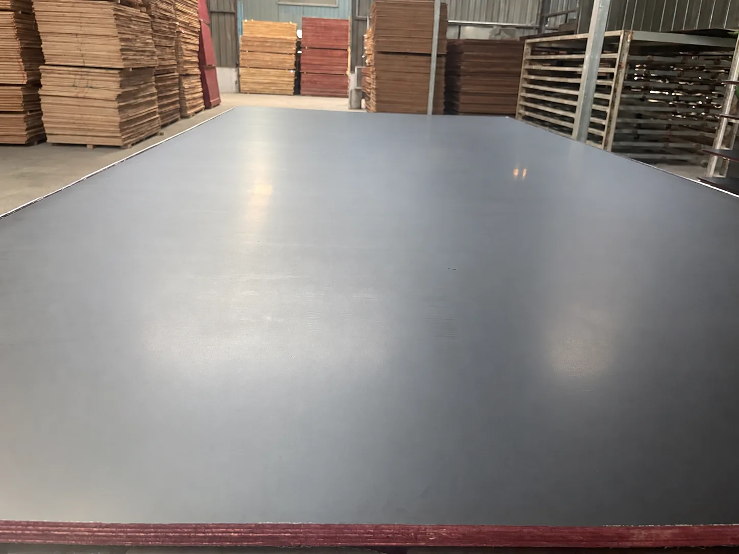
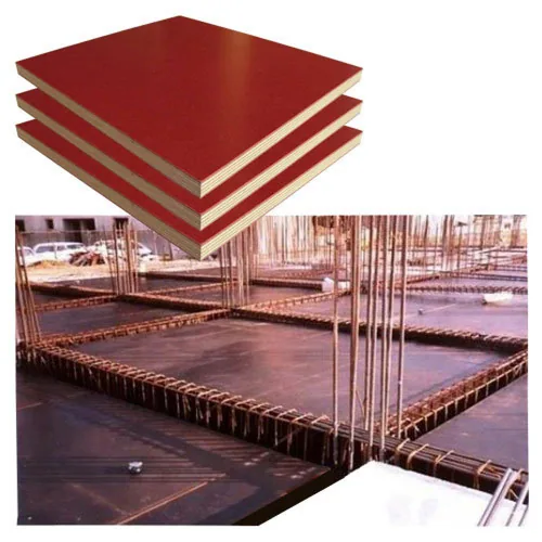
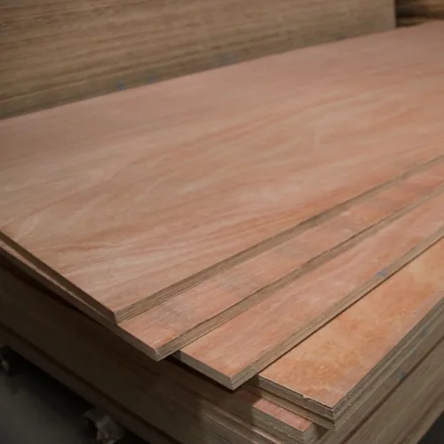
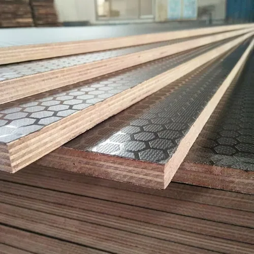
CUZI Anti-slip Plywood is available in 9–35 mm with poplar, eucalyptus, birch or mixed cores. Patterns include grid, rice, hexagonal and mesh; colours include brown, black and red, with a smooth film-faced reverse. Request the pattern and construction to be evaluated for your actual service conditions.
Use one template file for every floor position
Include the vehicle reference, panel ID, datum, overall outline, fixing holes, cut-outs, upper face and traffic direction. List quantities by position and identify whether the quote covers full sheets or prepared pieces. Ask for any changed thickness, core or cutting scope as a separate alternative.
CUZI container orders can mix panel items, making the schedule useful for repeat vehicle-production or replacement programmes. Send the quantity by vehicle type and destination port; confirm any surface tests and construction data your design requires.
Send one complete replacement brief
Attach the actual vehicle template, current part/quantity schedule and required material/surface data. Identify supplied cut/finished components versus the operations completed by your installer, selected spares, part/lot labels and named FOB/CIF port. Request a working sample and proposed data for the full construction before the repeat replacement programme is scheduled.
Keep these details with your inquiry
- Vehicle reference and labelled F1/F2-style positions.
- Dimensioned template, datum and working-face direction.
- Loads, supports, fixings and service conditions.
- Surface evaluation, edge details and proposed processing scope.
Review the relevant product guide and prepare your inquiry files.
Questions buyers ask
Can I order using thickness and anti-slip pattern alone?
No. Thickness and surface pattern alone do not define a suitable replacement floor. Those details leave the construction and complete floor duty open. Include the support and use information needed to review the proposed replacement.
Should the new panel copy every hole in the old floor?
Verify the current fixing arrangement and template. Record any design or vehicle modification before using old holes as the replacement instruction.
Should the drawing show the opening or the finished part size?
Record both and identify perimeter clearance, internal joints, profiles and the measurement stage. The actual vehicle template and agreed fit requirements determine the finished cut schedule.
Why should matching F1 and F2 parts have individual labels?
Their hole patterns, position, traffic and joint details can differ. Retain the installed position, current template, upper face/front and full material reference for each piece.
Can a printed anti-slip pattern code replace surface test details?
No. A pattern code identifies a surface but does not establish slip or wear performance. Use the pattern code to identify the actual proposed surface, then request the relevant method, orientation, conditions, specimen and results for the duty being assessed.
What should I keep for a repeat fleet order?
Keep vehicle/part/drawing revisions, measured template, full construction/data scope, fitted edge/joint/fastener detail, surface reference and quantity/pack schedule. Review changes before allocating another batch.