Specifications
Supply specifications
Finished panel formats
Send your required width and length. Available formats are confirmed with the selected panel and quoted scope.
Buying components?
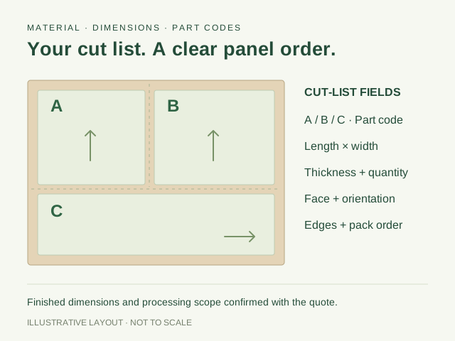
Include part dimensions, grain direction and quantities by item with your drawing.
| Machining service | MDF machining available; discuss your drawing and required operations |
|---|---|
| Board & thickness | MDF grade and processing thickness confirmed with the proposed part |
| Profiles & features | Section, positions, depth, datum and drawing revision |
| Tolerance | Confirmed for the drawing, selected board and inspection conditions |
| Finish & fitting | Delivered preparation, coating/facing and hardware or installation references |
| Quantities & packing | Part codes, handed sets, trial format, feature protection and bundle schedule |
Application-specific specification checks
Panel construction and finishing
| Drawing reference | Part code, revision, units, datum, handed parts and critical section. |
|---|---|
| Feature geometry | Holes, profiles, grooves, slots and perforation pattern by position, dimension and depth. |
| Processing proposal | Requested operations, availability, thickness limits and tolerances confirmed against the drawing and quotation. |
| Finish and fit | Visible faces, machined surface, coating or facing, hardware and complete-component trial. |
| Packing and order | Protected features, matched or handed sets, part labels, item quantities and receiving schedule. |
Make the drawing and the part schedule agree.
Use one part code and revision across the drawing, quotation and sample. State the units, finished dimensions, datum face and the quantity required for each handed or mirrored component.
| Board selection | MDF designation, grade, thickness, facing and the destination or application requirements. |
|---|---|
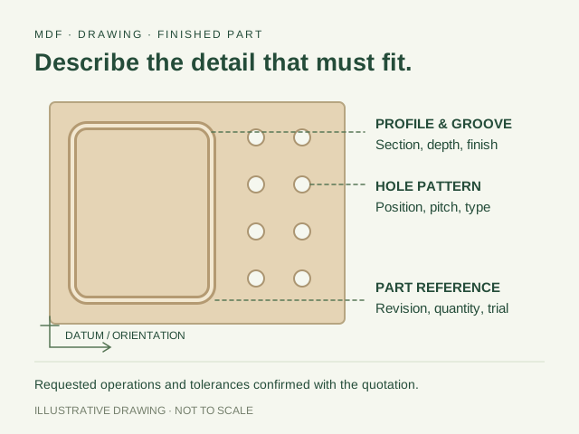
| Part geometry | Finished length, width, thickness, outlines, datum edges and a section through critical profiles. |
| Holes and recesses | Hole type, diameter, position, pitch, depth, through/blind detail and the hardware or fitting reference. |
| Grooves and slots | Width, depth, spacing, direction, corner detail and the material remaining behind the feature. |
| Tolerance and finish | Critical dimensional limits, measurement conditions, visible faces, profile preparation and the finishing scope. |
| Quantity and packing | Parts by code, left/right sets, trial quantity, labels, protection and bundle sequence. |
Requested operations, available processing thickness and achievable tolerances are confirmed for the proposed job. Include a physical fitting or dimensioned hardware reference when the part must mate with another component.
Give every feature a reference face and a measurement stage.
Scroll horizontally to compare all columns.
| Reference | Put on the drawing | Use at the trial |
|---|---|---|
| Datum edges and face | Named reference edges, front/reverse view and the origin used for feature positions. | Measure from the same edges and face, with left/right components identifiable. |
| Feature definition | Diameter or width, centre position, depth, through/blind detail and a section where needed. | Check the defined feature and its mating hardware, not only the overall rectangle. |
| Internal corners | Required corner shape, radius or clearance and the mating-part detail. | Try the actual joint or insert so the corner does not obstruct assembly. |
| Delivered condition | Before or after edging, sanding and coating; tolerances for the relevant stage. | Record the measured stage and remaining operations with the part revision. |
Dimension holes from a common datum when their positions must relate to the same fitting. Include the hardware drawing or physical reference, with the load and use relevant to the joint. A diameter and a depth describe geometry; fitting selection and assembly performance also need the proposed board and completed joint.
For blind holes or grooves, state where the depth is measured from and what material must remain behind it. Identify visible-face protection, entry and exit faces for through features, and any intersecting operations. Do not leave a front view to stand in for the section through a critical recess.
SELECT THE BOARD WITH THE MACHINED DETAIL
Choose the substrate your part and finish require.
Standard MDF
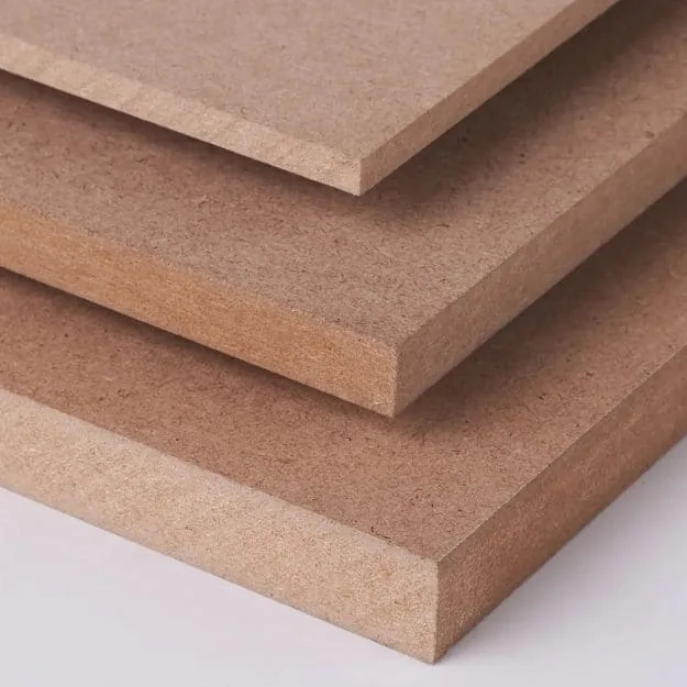
Plain MDF is available in 2.5–35 mm with E0, E1 or E2 options. Select the thickness and board requirement for your application; confirm the proposed machining and finishing with its trial.
Review standard MDFMoisture-resistant MDF
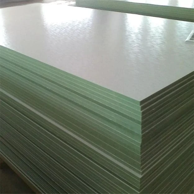
Our unfaced MR board range is 9–25 mm with E0 or E1 options. Describe the expected exposure and the treatment of machined edges, cut-outs and later finishes.
Review MR boardFire-retardant MDF
The FR board range is 9–25 mm with E0 or E1 options. Identify the required standard, classification and complete construction, including machined patterns and decorative finishes.
Discuss FR requirementsThese are board supply ranges. The material, remaining section, surface and requested operations determine the machining proposal for your drawing. For faced boards, also identify the reverse, edge treatment and permitted face damage in the sample criteria.
Keep any alternative board or processing scope on a separate quotation line. Compare the same delivered part, including your own preparation, coating, assembly and rejected-part allowances.
If the slots are intended for forming a curved part, use the Flexible MDF curve inquiry to define the radius, bend direction, layer build-up and final facing alongside the requested machining.
Connect cutting depth with the remaining section.
The simple geometry below uses a measured 18 mm board and one blind cut from a single face. It helps describe the requested section; it does not choose a safe depth for a loaded component or establish machining tolerance.
Scroll horizontally to compare all columns.
| Measured board thickness | Blind-cut depth | Remaining material |
|---|---|---|
| 18 mm | 6 mm | 12 mm |
| 18 mm | 9 mm | 9 mm |
| 18 mm | 12 mm | 6 mm |
Remaining material equals measured board thickness minus cut depth at that feature. Include tolerances, both-side operations and the real section in the job discussion. For a faced or coated part, distinguish total finished thickness from the MDF core and identify which surface is the depth reference.
Select the board around that section, the intended fixing and the completed finish. Density information is useful alongside the machining trial, but it does not replace a trial of a narrow profile, exposed edge or connector joint on the offered material.
COMPARE OPTIONS
Your selection at a glance
Drawing and geometry
Include the revision, units, datum, feature positions, section, depth and material remaining behind the profile.
Board and delivered scope
Specify the MDF grade, thickness, face and finishing work. Processing details and tolerances are confirmed for the proposed job.
Trial and assembly
Connect the machined feature to hardware, coating or installation checks, with a retained part and agreed packing labels.
TRIAL THE FEATURE THAT DECIDES THE ORDER
Bring the profile, fitting and finish into one trial.
- Identify the critical featureChoose the recess, edge profile, connector hole or repeated pattern that determines whether the component works.
- Agree the proposed partConfirm board choice, processing, dimensions and trial format with the drawing revision. Include the work your workshop will carry out.
- Evaluate the complete detailMeasure the agreed features, try the hardware or finish and retain the selected component with its inspection record.
Material samples are free under our board-sample arrangement, with buyer-paid freight and a possible later-order credit. Machined trial parts, requested operations and their delivery are arranged for the specific project.
For painted fronts, use the routed MDF finishing guide to record the board, profile and finish sequence. For assembly details, follow the hardware and panel trial.
Bring the feature, fitting and measurement stage into the request.
Choose the detail that decides assembly or finish. The 18 mm entries request an unfaced board gauge within the stated board range; the actual machined section, processing limits, tolerances and delivered finish are agreed for the drawing. Machined trial parts and operations are quoted for the job under the arrangement above.
Scroll horizontally to compare all columns.
| Critical detail | Reference to keep | Start the request |
|---|---|---|
| Painted routed front | Requested standard 18 mm E1 board; deepest profile, internal corner and reverse operations, measured remaining material, preparation/primer/topcoat/cure and actual finished fitting. | Discuss the routed-front trial |
| Four-hole reverse datum | 400 × 600 mm drawing and H1–H4 schedule below; lower-left reverse datum, 5 mm diameter and 12 mm blind depth. Confirm actual fitting, measured section, limits and separately labelled mirrored part. | Discuss the four-hole component trial Request the board and feature file |
| Groove with its finished insert | Requested 18 mm MR E1 board; actual insert thickness and finish, groove width/depth/start/end, corner clearance and remaining section. Compare blank, machined and finished-part supply separately. | Quote the groove-and-insert parts |
Complete the operation your production line depends on.
For a painted profile, apply the intended preparation and coating to the routed face, edge and internal corner, then inspect after the finish has reached its specified condition. For a fitting, use the actual hardware and mating part. Keep the measured feature, assembly result and remaining workshop work together.
The European Panel Federation’s routing guidance relates cutting conditions and tooling to edge quality. Choose the proposed process with the material and profile rather than transferring one universal feed rate or finish allowance to every component. Retain the selected part with its board, tool/process reference where relevant, and finished appearance record.
Acceptance worksheet
Keep a record your workshop and purchasing team can use.
Link the board sample, machined component and drawing to the same part code. Agree the criteria before evaluating the proposal, then record observations against the relevant feature.
Open the MDF machining trial worksheet
| Check | What to record |
|---|---|
| Part identity | Drawing revision, part code, units, board grade, thickness, face and trial reference. |
| Geometry and datum | Measurement method, finished size, critical profile section, datum and proposed tolerance. |
| Holes and slots | Feature type, positions, depth, remaining section, border detail and connector fit. |
| Machined surface | Profile marks, loose fibres, exposed edges, face breakout and preparation required before coating. |
| Finished assembly | Coating or facing reference, joint and hardware fit, viewing conditions and complete-part result. |
| Order and packing | Quoted operations, unresolved changes, handed sets, labels, quantities and protected features. |
| Depth reference | Measured board/core thickness, reference face, feature depth and remaining section; both-side operations where relevant. |
| Repeat purchase | Retained part, agreed revision, fitting and finish reference; material or process changes requiring a new component check. |
MATERIAL DATA AND THE COMPONENT DRAWING
Connect the board requirements to the finished assembly.
Include your application and destination when requesting the material and processing documents. A board report, component drawing and installation requirement answer different purchasing questions.
The European Panel Federation’s MDF routing guidance discusses tooling and cutting conditions. Use the selected board and representative profile to agree machining and finish checks for your project.
Where a project specifies fire or acoustic performance, request documents matching the complete construction and installation you intend to buy. Describe changes to perforations, coatings, backing and fixing in the document discussion.
Keep a readable drawing alongside the production file.
Use the same part code and issue on the PDF, cutting schedule and any agreed machine file. State the units and resolve conflicts between views, written dimensions and the part list before the processing scope is fixed. Identify dimensions that control assembly and the measurements intended at receiving.
Request the selected board designation, grade, thickness range, density requirement and emission method with the drawing. Add documents for the actual facing or completed system where the project requires them. If board, profile, finish or installation changes, identify the changed requirement on the revised item.
Product data & reports to request
Request a technical data sheet covering:MDF designation, grade, thickness, surface, destination and required test methods for the proposed construction.Include these specification details:- Board designation, grade, thickness, emissions and applicable test methods
- Drawing revision, datum, units, feature dimensions and section details
- Requested processing, proposed tolerances and inspection conditions
- Coating, facing, hardware, backing and installation references
- Trial part, technical-document requirements and repeat-order item code
Company documents to view
FSC chain of custody Wood panels · purchase & salesISO 9001 & ISO 14001 Management systems · stated sales activitiesUse these for supplier qualification; match product performance to the proposed panel’s technical documents.MDF component and machining requirements: what to match
- Board and application
- MDF designation, grade, thickness, surface, destination and required test methods for the proposed construction.
- Drawing and quoted processing
- Part code, revision, datum, profiles, holes, depths and requested tolerance; processing details and included operations confirmed in quotation.
- Trial and complete assembly
- Representative machined feature, finish, fitting or installation; agree measurement, appearance and packing checks with the selected part.
BEFORE YOU ORDER
Board-order reference
Regular board supply is summarised below. Your quotation confirms the included machining operations, part trial and job schedule.
- Minimum order
- 1 container
- Regular lead time
- 10–15 days
- Samples
- Free samples
- Quotation terms
- FOB / CIF
Sample freight & order notes
- Minimum order: Mixed loads available.
- Regular lead time: Production; shipping time is additional.
- Samples: Buyer pays freight; credit available on a later order.
- Quotation terms: Name the port in your inquiry.
PROTECT THE FEATURE YOUR TEAM WILL ASSEMBLE
Keep machined parts identifiable in each pack.
Include protection for projecting profiles, corners, decorative faces and narrow or perforated sections in the packing discussion. Identify left/right pieces, paired fronts and installation sequences with the agreed part labels.
On receipt, reconcile the item quantities and drawing revision before assembly. Record pack condition, visible damage and the agreed feature measurements with the bundle reference; retain observations for any follow-up.
Specify unloading constraints, bundle sequence and handling needs in the quotation. The incoming-panel checklist helps organise the receiving record.
Receive by part code and drawing issue.
Reconcile counts before mixing packs. Keep mirrored parts and assembly sets distinguishable, with protection around projecting or narrow features. Check the agreed dimensions and critical holes or profiles on the receiving plan, then connect any observation to the part and pack label.
For repeat supply, keep the retained component and its fitting, finish and drawing references available to purchasing. Issue the updated specification when a profile, board, hardware or finish changes; a familiar product name alone does not describe the new component.
THE DETAIL YOUR PRODUCTION LINE NEEDS
Start with the drawing. Keep the finished part in view.
Choosing the substrate for a routed or finished part? Our MDF process and quality guide connects grade, density information, sanding and thickness with the drawing, working sample and proposed board data.
Choosing the substrate for that part? Compare MDF and HDF on the same component detail, with the offered board data, machining and finished result kept together.
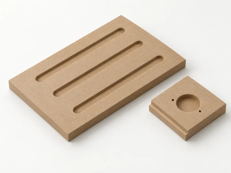
A shaped edge, hardware hole or repeated groove needs a clear reference. Discuss your MDF component with CUZI using the board, drawing and finish that belong together.
Send the part you want quoted, including the operations performed before delivery and the work your workshop will complete. CUZI supplies machined MDF components around your drawing. The quotation connects the selected board, included operations, tolerances and delivery arrangement.
Use this page for MDF routing, grooved or slotted details, drilling and perforation inquiries. For rectangular blanks, start with the cut-to-size panel page. For sheets to process yourself, compare our Plain MDF board options.
For an acoustic interior, use the acoustic MDF project route to connect holes or slots with the face, backing and installation section. Include the required absorption report and the components you want supplied with your drawing.
For a door-facing style, use the MDF door skin purchasing brief to specify the model/master and formed geometry. This connects the delivered facing with its assembly, while the machining route defines operations on a separately drawn part.
For a cabinet-door component, moulding or skirting/baseboard profile, the finished-component brief connects the drawing, included operations and delivered-part sample.
Bring purchasing and production together around the feature that decides the order. For a cabinet front, that may be the coated profile. For a carcass part, it may be a connector hole or a groove receiving the back. Describe the finished fit first, then connect it to the material and delivered operations.
ONE MACHINED DETAIL. A COMPLETE COMPONENT.
What does your drawing need to achieve?
Routed furniture fronts
Define the perimeter, profile section and recessed detail with the intended coating system. Evaluate the actual routed edge, corners and reverse face on a representative component.
Hardware and assembly parts
Show the datum, hole positions and handed parts with the intended connector or fitting. Trial the joint and assembled alignment using the specified hardware.
Grooved, slotted or perforated panels
Describe the pattern, depth or through-cut, direction and border treatment. Include backing, installation and any required system documents where the panel belongs to a larger assembly.
For an acoustic application, request the test documentation for the complete proposed installation, including backing and mounting. A hole pattern alone does not establish a sound-absorption rating.
Define the process around the completed feature.
Scroll horizontally to compare all columns.
| Component route | Drawing and finish detail | Trial question |
|---|---|---|
| Routed front or moulding | Profile section, internal corner, visible face, delivered preparation and coating sequence. | Does the selected finish give the appearance required on the routed surface and edge? |
| Drilled assembly component | Hole identity, datum positions, diameter/depth, fitting and handed part code. | Does the completed joint align and fit with the intended hardware? |
| Grooved backing detail | Groove section, receiving-board thickness, start/end positions and remaining material. | Does the actual back or insert fit at its finished thickness? |
| Slotted or perforated face | Pattern, open and solid borders, support, backing, fixing and surface treatment. | Does the proposed assembled panel meet the project’s appearance and system requirements? |
Keep a repeated pattern connected to the borders and fixing zones. Specify how the pattern meets corners, access panels and adjoining parts. A dimensioned elevation and section can communicate those relationships more clearly than a photograph of the pattern alone.
A ROUTED FRONT. A SHARED PART REFERENCE.
Describe the detail from machining through coating.
- Drawing reference
- Part code, revision, front/reverse view, datum and a section through the demanding profile.
- Material proposal
- MDF grade, thickness and emission requirement, with the board’s documents and sample reference.
- Delivered scope
- Requested machining, proposed tolerances, profile preparation and the finishing work your workshop will complete.
- Trial decision
- Measured profile, cured coating appearance, hardware fit and the retained complete front linked to the quote.
A changed profile or coating can alter the trial you need. Identify the affected features with the next drawing revision and keep the chosen part, material and delivered scope together for repeat purchases.
A hole-position schedule makes the datum visible to every team.
Take a 400 mm-wide × 600 mm-long panel with four requested blind holes. Set the origin at the lower-left corner of the designated reverse face: X across the width and Y along the length. The planning coordinates below place two rows at Y = 100 and 500 mm, and two columns at X = 37 and 363 mm.
Scroll horizontally to compare all columns.
| Hole code | X from left datum | Y from bottom datum | Requested feature |
|---|---|---|---|
| H1 | 37 mm | 100 mm | 5 mm diameter; 12 mm blind depth from reverse |
| H2 | 363 mm | 100 mm | 5 mm diameter; 12 mm blind depth from reverse |
| H3 | 37 mm | 500 mm | 5 mm diameter; 12 mm blind depth from reverse |
| H4 | 363 mm | 500 mm | 5 mm diameter; 12 mm blind depth from reverse |
The column-centre distance is 326 mm and the row-centre distance is 400 mm. Each column is 37 mm from its nearest side; each row is 100 mm from its nearest end. On a measured 18 mm board, a measured 12 mm blind depth leaves 6 mm behind the hole. These numbers define this geometry, not a standard hardware pattern or an available machining tolerance.
Attach the fitting reference, position and diameter limits, depth tolerance and a section to turn the schedule into a job request. Identify how a mirrored component is viewed and labelled; do not infer the handed part from the same front-view drawing. Trial the completed assembly before fixing the production item.
FROM THE TRIAL TO THE PURCHASE SCHEDULE
Quote the same drawing your workshop will use.
List parts by drawing revision, board, thickness, finish and required operations. Separate trial quantities from the intended production schedule, and identify any matching sheets or other panels for a proposed mixed load.
Regular CUZI board orders start at one container, with mixed loads available and regular production of 10–15 days before shipping. The machined component’s batch quantity, trial, operations and schedule are confirmed in its quotation.
Request FOB or CIF with the named port and target receiving date. Use the mixed-panel order schedule to coordinate component codes, material lines and packing.
Compare the component ready for the same next operation.
Ask each offer to name the board, drawing issue, included features, tolerances and delivered preparation. Show sanding, coating, edging, hardware and assembly operations that remain outside the quoted supply. Keep alternative boards or profiles on distinct item lines.
Compare total cost per usable component at your next workstation, including material, processing, protective packing, transport and the work your team still performs. State the production quantity separately from the trial. Confirm how drawing changes, extra features or revised surface preparation affect the quoted scope and schedule.
FAQ
Questions before the machining discussion.
Can I ask about CNC MDF routing, holes and grooves?
Send the drawing with the operations you want included. Equipment suitability, processing limits, tolerance and delivery scope are confirmed for the proposed job.
Is grooved, slotted or perforated MDF one product?
These names describe different features. Specify the pattern, section, depth or through-cut, spacing, board and intended use so the proposal follows the component you need.
Does perforated MDF have an acoustic rating?
Request acoustic data for the specified board, backing and mounting arrangement. The perforation drawing describes geometry; performance documents should match the complete proposed system.
Which thickness and tolerance should I specify?
Identify the board thickness, feature dimensions and the limits needed for fit or assembly. Available processing thickness and tolerances are agreed with the drawing and trial, including remaining material behind grooves or recesses.
Do MR or FR board options cover every machined detail?
Select the material for its use, then request the documents and trial for the proposed machined construction. Include exposed edges, finishes, patterns, fixing and installation conditions in that discussion.
How should I send the drawing?
Begin with the material, part description, quantity and destination in the inquiry form. Email the drawing or use the file-sharing guidance; include units, revision and datum. Agree the production-file format with the processing proposal.
Can I order boards for machining in my own workshop?
Yes. Request the required MDF board grade and sheet format, then trial your own profile, tooling and finish. Keep board supply and any requested external processing as distinct lines in the purchase schedule.
How do I specify a machined MDF component?
Start with the board, drawing revision, datum and dimensions. Describe holes, grooves or profiles, quantities, required tolerance and finishing scope. The proposed processing and trial are confirmed for your part.
Request a quote
Send the drawing. Tell us which detail matters.
A part description, MDF requirement, approximate quantity and destination can start the conversation. Add the drawing and the operations you want quoted as the project takes shape.
Open the MDF machining inquiry outline
MDF machining inquiry: [component and intended application].
Material: [MDF designation, board grade, thickness, surface and emission requirement].
Drawing: [part code, revision, units, datum, views and profile section].
Part quantity: [codes; handed pairs or sets; trial and production requirements].
Requested operations: [routing, holes, grooves, slots, perforation pattern or edge work to discuss].
Features: [positions, width/diameter, depth, pitch and remaining material].
Depth basis: [reference face, actual board/core thickness and remaining section].
Critical fit: [hardware or joint reference; tolerance and inspection conditions].
Finish: [delivered preparation; coating/facing and work to complete in our workshop].
Trial: [representative feature, material/part sample and assembly checks].
Documents: [destination market, required methods, application and installation].
Cost and handover: [included preparation; remaining workshop operations; usable components required].
Packing: [protected features; part labels; paired sets and bundle sequence].
Quotation: [included processing and scope]; FOB or CIF [named port]; [receiving date].
Download the machining inquiry (.txt)